This one was acquired in 2003 and is the «October 2003» model runing at 933 MHz
Model Identifier PowerBook6,3
Model Number A1055 (14.1-inch)
Order Number M9388LL/A (14.1-inch 933 MHz)
After the logic board died for the well known defect to the logic board (iBook G4 Motherboard Vreg Chip Solder Joint Repair) I found for a good price a 1.33 logic board and try to fix the iBook.
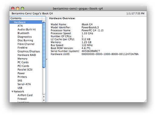
The new logic board came from a «late 2004» model runing at 1.33 GHz:
Model Identifier PowerBook6,5
Model Number A1055 (14.1-inch)
Order Number M9627LL/A (14.1-inch Combo), M9628LL/A (14.1-inch SuperDrive)
After disassebling the iBook (https://www.ifixit.com/Guide/iBook+G4+14-Inch+933+MHz-1.33+GHz+Logic+Board+Replacement/197) I realized that there is a lot to do:
1) the following connectors are different:
a) optical drive ribbon - a new ribbon is needed;
b) top case connections (speakers, power and trackpa cables) - a new top case is required;
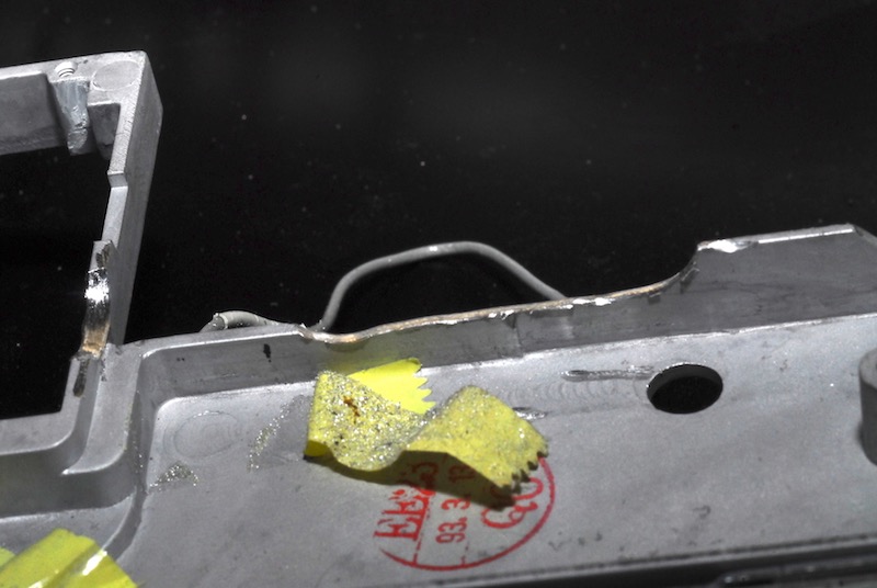
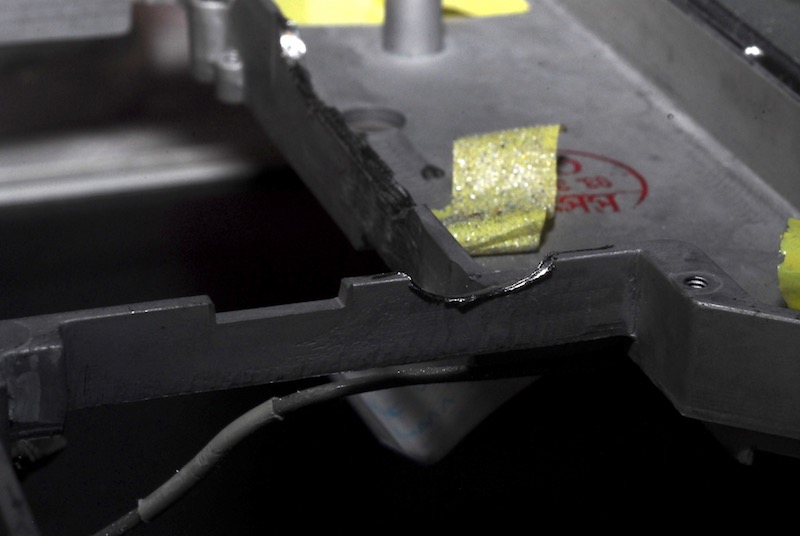
2) the metal frame is different so you have to dremel in several places especially where the optical drive ribbon connects to the logic board - some tabs have to be removed too;
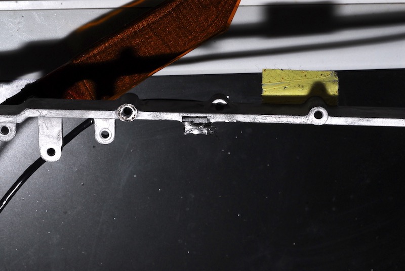
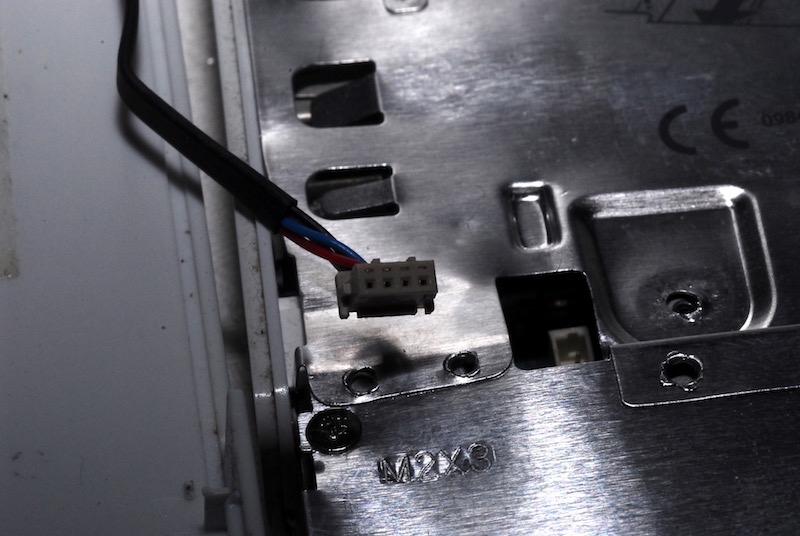
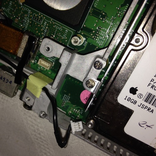
3) the fan cable is shorter, but the connector is the same, so here we just need to solder a fee inches wires to reach the new position of the connecto in the logic board - no need to buy a new cable
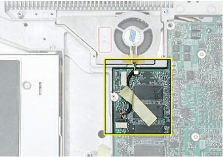
933 MHz fan cable
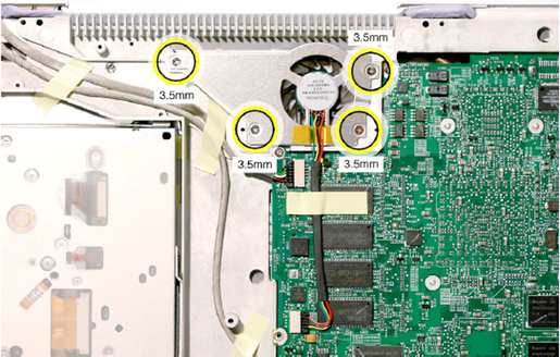
1.33 GHz fan cable
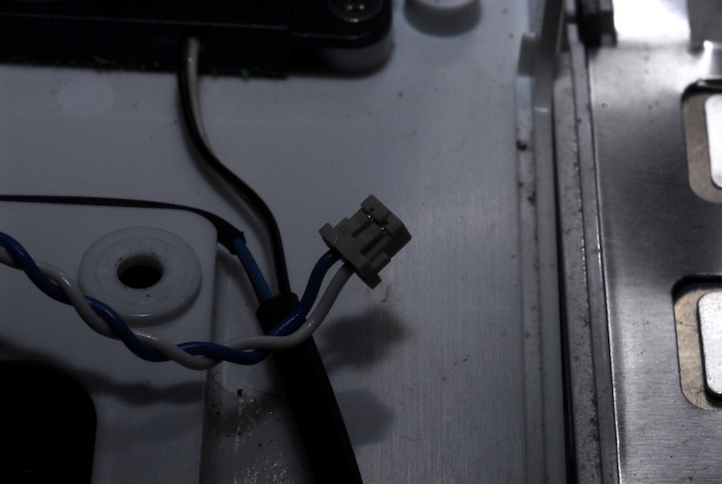
4) The modem is completely different and the LVDS cable has a specific route which is different from the 1,33 GHz model. I guess that without a new LVDS cable it is impossible to insert the 1.33 modem - I opted for no modem, we are in 2016...
933 LCD cable
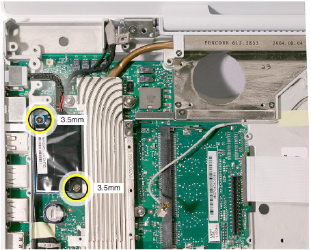
1.33 LCD cable
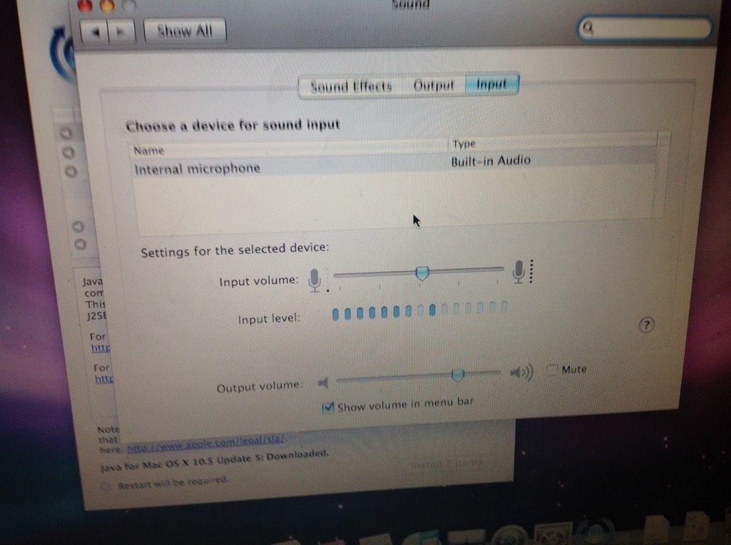
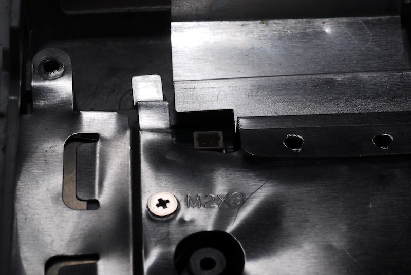
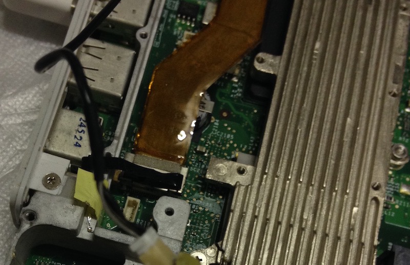
Finally, my new logic boars had a defect (luckily the eBay seller agreed to reimburse me with 60% of the price): the microphone connector was missing (these connectors are are attached very firmly to the sockets on the logic board and pulling directly on the cable will either separate the cable from its connector or the socket from the logic board - this is what happened to previous user). So I decided to solder three small wires to the three contacts in the logic board and use them as extensions to reach the microphone cable.
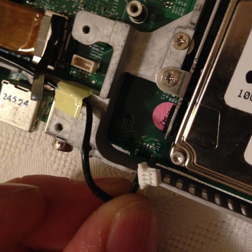
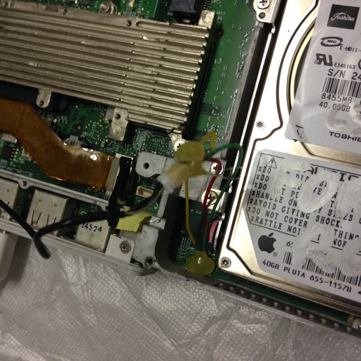
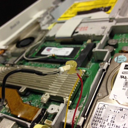
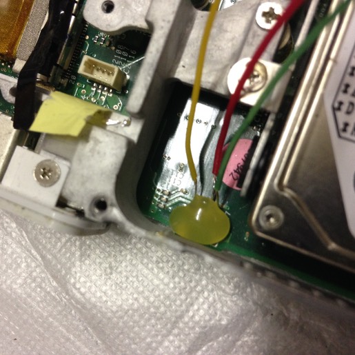
The microphone works, no big deal but it is interesting to know.